The correct wiring method for the encoder:
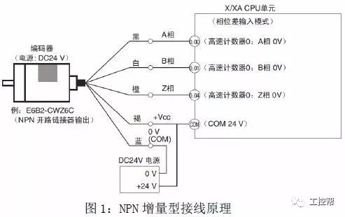
(1) Correct wiring is very important. Figure 1 shows the wiring principle of the NPN output incremental type E6B2-CWZ6C. Figure 2 shows the actual wiring of the NPN output incremental type E6B2-CWZ6C. The brown line is connected to the positive pole of the power supply and the blue line is connected. The negative pole of the power supply, the black line is connected to input 0.00, the white line is connected to input 0.01, the orange line is connected to input 0.04, and the PLC's COM is connected to the positive pole of the power supply.

(2) The following figure shows the actual wiring diagram of the PNP output incremental type E6B2-CWZ6B. The brown line is connected to the positive pole of the power supply, the blue line is connected to the negative pole of the power supply, the black line is connected to input 0.00, the white line is connected to input 0.01, and the orange line is connected to input 0.04. The COM of the PLC is connected to the negative pole of the power supply.

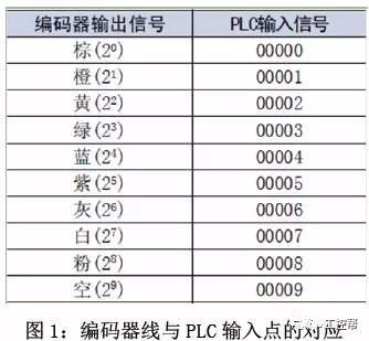
(3) Figure 1 is the corresponding diagram of the line of the absolute value encoder and the point of the PLC input. Figure 2 is the actual wiring diagram of the absolute value type E6C3-AG5C of the NPN output. The red line is connected to the positive pole of the power supply, and the black line is connected to the negative pole of the power supply. Brown line input is 0.00, orange line is input 0.01, yellow line is input 0.02, green line is input 0.03, blue line is input 0.04, purple line is input 0.05, gray line is input 0.06, white line is input 0.07, pink The line is connected to input 0.08, and the COM of the PLC is connected to the positive pole of the power supply.

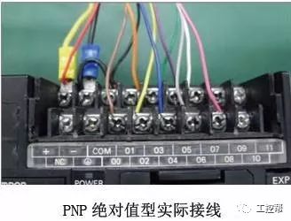
(4) The following figure shows the actual wiring diagram of the PNP output absolute value type E6C3-AG5B. The red line is connected to the positive pole of the power supply, the black line is connected to the negative pole of the power supply, the brown line is connected to the input 0.00, the orange line is connected to the input 0.01, the yellow line is connected to the input 0.02, green. Line input is 0.03, blue line is input 0.04, purple line is input as 0.05, gray line is connected to input 0.06, white line is connected to input 0.07, pink line is connected to input 0.08, and PLC's COM is connected to negative power supply.
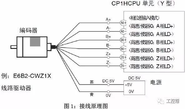
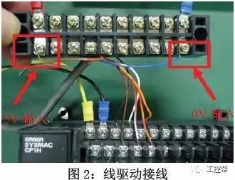
(5) Figure 1 shows the wiring principle of the line drive encoder. Figure 2 shows the actual wiring diagram. The black line is connected to A0+, the black and red line is A0-, the white line is connected to B0+, the white and red line is connected to B0-, and the orange line is connected to Z0+. , orange red trim line is connected to Z0-, brown line is connected to power supply +5V, blue line is connected to power supply 0V, no wiring error.